Note: As an option, insulation can be added below the soil barrier. Insulation cannot, however, be added in/below the floor system because this thermal barrier defeats the purpose of a conditioned crawlspace and can set up a dangerous condition where the mechanically vented crawlspace becomes cold enough to produce condensation.
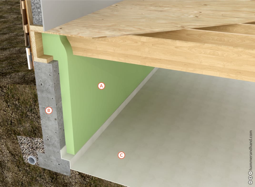
a. MEDIUM DENSITY SPRAY FOAM (MDSPF)
B. STEM WALL
C. 12 MIL REINFORCED SOIL BARRIER WITH JOINTS LAPPED, TAPED, AND SEALED
Ventilation: Code requires 1.0 CFM of continuous mechanical exhaust is required for each 50 square feet. For example, a 1000sf crawlspace will need 20cfm of ventilation. Ideally this is provided by a Heat Recovery Ventilator (HRV).