Skip to content
Services
Residential
Kitchens and Bathrooms
Remodel
New Home Build
ADUs
Basements
Condos and Lofts
Commercial
High Performance
Woodshop ▸
Windows & Doors
High Performance Doors
Furniture & Built-ins
Our Company
About Us
Meet our Team
Careers
Community Impact
In the Press
Awards & Affiliations
Testimonials
Resources
Blog
Videos
Best Practices Manual
High Performance 101
Portfolio
Contact Us
Contact Us
7. Basements
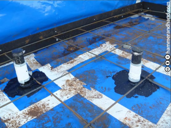
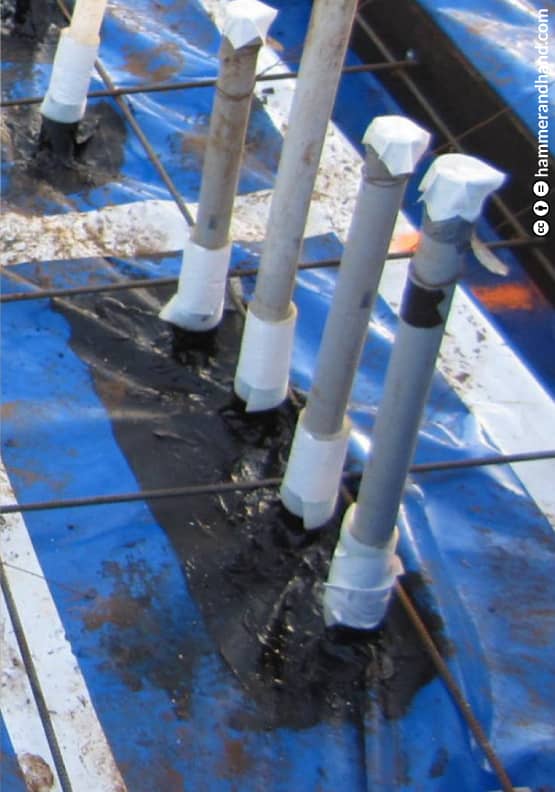
7.3 BASEMENTS: SUB SLAB VAPOR/SOIL-BARRIER
1. Flashing
1.1 FLASHING
1.2 HEAD FLASHING
2. Sealant Joints
2.1 SEALANT JOINT DESIGN
3. Windows & Doors
3.1 NEW WINDOW INSTALLATION
3.2 WINDOW RETROFIT
3.3 WINDOW BUCK IN A MASONRY WALL
3.4 DOOR INSTALLATION
4. Rain Screens
4.1 RAIN SCREENS: TOP OF WALL
4.2 RAIN SCREENS: TOP OF WINDOW
4.3 RAIN SCREENS: BOTTOM OF WINDOW
4.4 RAIN SCREENS: BOTTOM OF WALL
4.5 RAIN SCREENS: GABLE END
4.6 HORIZONTAL RAIN SCREEN FURRING FOR VERTICAL SIDING
5. Envelopes
5.1 WALL PENETRATIONS
5.2 AIR SEALING
5.3 INSULATION
5.4 EXTERIOR CONTINUOUS INSULATION (CI) AT WALLS
5.5 WALL ASSEMBLY EXAMPLE
6. Roofs
6.2 VENTED AND UNVENTED ROOF ASSEMBLIES
6.3 PARAPET WALLS
6.4 FLAT ROOF ASSEMBLIES
7. Basements
7.1 BASEMENTS: NEW CONSTRUCTION
7.2 BASEMENTS: CAPILLARY BREAK
7.3 BASEMENTS: SUB SLAB VAPOR/SOIL-BARRIER
7.4 BASEMENTS: RETROFIT
8. Crawlspaces
8.1 CRAWLSPACES: GENERAL GUIDELINES
8.2 NEW CONSTRUCTION: CONDITIONED CRAWLSPACE WITH INSULATED SLAB
8.3 RETROFIT OPTION 1: CONDITIONED CRAWLSPACE WITH SOIL BARRIER
8.4 RETROFIT OPTION 2: VENTED CRAWL WITH FLOOR ENCAPSULATION
9. Structure
9.1 DECK LEDGERS
9.2 POCKET DOOR FRAMING
9.3 STAIR FRAMING
10. Acknowledgements
10. ACKNOWLEDGEMENTS
Taped seams and sealed penetrations in the sub slab vapor and soil barrier.
More resources
High Performance 101
Blog
Services
Residential
Commercial
High Performance
Woodshop
Residential
Commercial
High Performance
Woodshop
Company
About Us
Meet our Team
Careers
Community Impact
In the Press
Awards & Affiliations
Testimonials
About Us
Meet our Team
Careers
Community Impact
In the Press
Awards & Affiliations
Testimonials
Portfolio
Residential
Commercial
High Performance
Woodshop
All Projects
Residential
Commercial
High Performance
Woodshop
All Projects
Resources
Blog
Videos
FAQs
Best Practices Manual
High Performance Building 101
Blog
Videos
FAQs
Best Practices Manual
High Performance Building 101
Contact Us