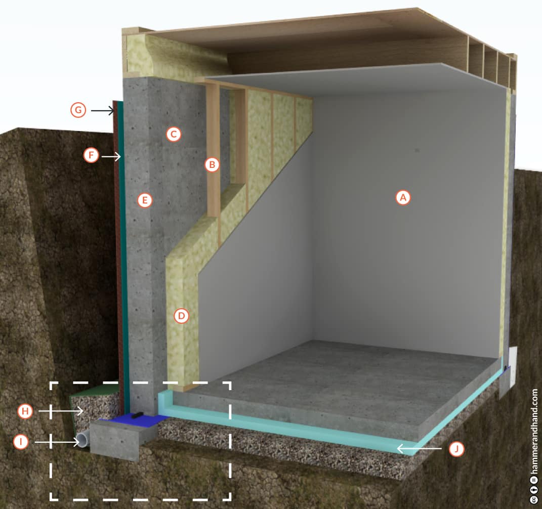
A. DRYWALL
B. 2X4 STUD WALL
C. 1- 2 1/2” GAP BETWEEN STUD WALL AND FOUNDATION WALL
D. LOW OR MEDIUM DENSITY SPRAY FOAM INSIDE AND BEHIND STUD WALL
E. FOUNDATION WALL
F. FLUID APPLIED ELASTOMERIC MEMBRANE
G. DIMPLED DRAINAGE MEMBRANE WITH GEOTEXTILE FABRIC
H. MINIMUM 4” LAYER WASHED AND CLEANED (NO FINES) CRUSHED STONE OR GRAVEL
I. 4” DRAINAGE PIPE, HOLES DOWN
J. 2-4” RIGID INSULATION
K. NOT SHOWN: IF RIGID FOAM INSULATION IS USED ON AN EXTERIOR WALL, PROTECT THE TOP WITH A COATING OR PROTECTION BOARD. BELOW GRADE, PLACE INSULATION BETWEEN DIMPLE DRAINAGE MAT AND ELASTOMERIC WATERPROOF MEMBRANE. FOAM MUST BE PROTECTED WITH DURABLE FINISH WHEN EXTENDED ABOVE GRADE.
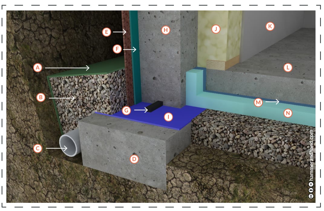
A. HEAVY DUTY GEOTEXTILE FILTER FABRIC
B. WASHED GRAVEL FILL
C. 4” DRAINAGE PIPE, HOLES DOWN. ALWAYS LOCATE BELOW BOTTOM OF SLAB.
D. FOOTING
E. DIMPLED DRAINAGE MEMBRANE WITH GEOTEXTILE FABRIC
F. FLUID APPLIED ELASTOMERIC WATERPROOF MEMBRANE
G. EXPANDING JOINT WATERSTOP*
H. FOUNDATION WALL
I. FLUID APPLIED CAPILLARY BREAK (SEE SECTION 7.2)
J. LOW OR MEDIUM DENSITY FOAM
K. DRYWALL
L. FLOOR SLAB
M. 12 MIL REINFORCED SOIL BARRIER WITH SEALED SEAMS (SEE SECTION 7.3)
N. 2-4” RIGID INSULATION
*Waterstops should be installed at all joints below grade. Place water stop a minimum of 3” to the exterior surface of the wall.
Note: Utilize pipe cast into footings to interconnect sub-slab drainage zone.