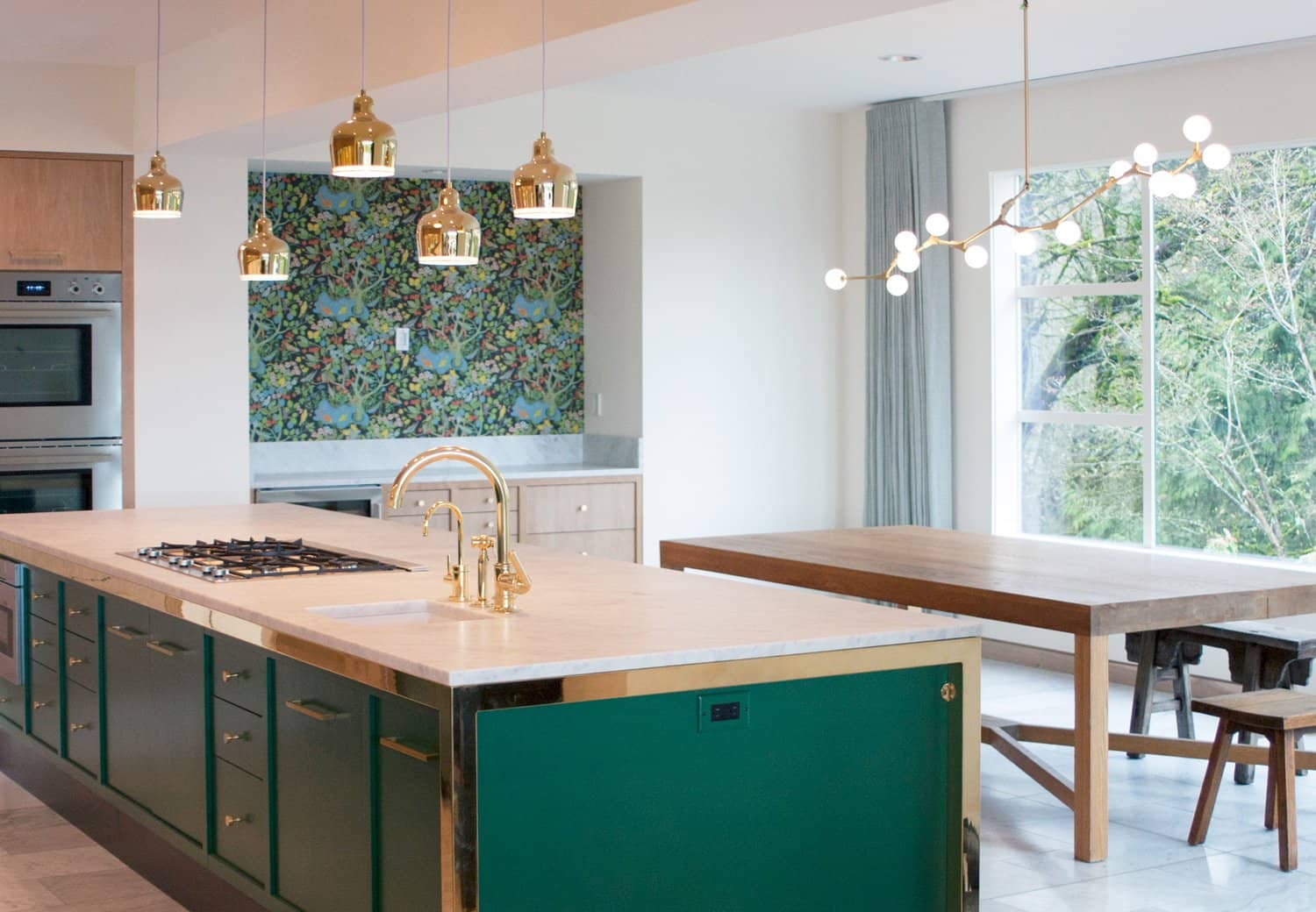
Forest Park House
SCOPE: Full Interior and Exterior Remodel Our client, a family looking to consolidate their residences and retire in Portland, enlisted us to help in creating their new space. They purchased


SCOPE: Full Interior and Exterior Remodel Our client, a family looking to consolidate their residences and retire in Portland, enlisted us to help in creating their new space. They purchased
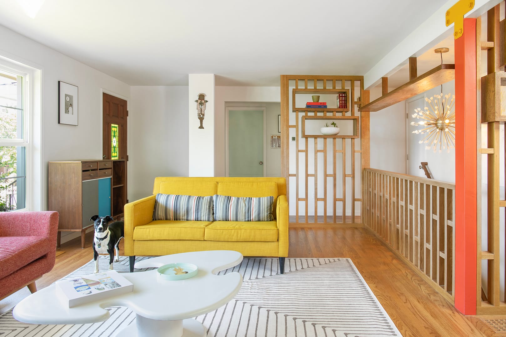
This 1950s brick rambler was transformed to align with a contemporary, work-from-home lifestyle while infusing the brightness of Southern California. The renovation opened up the layout, featuring a sculptural screen
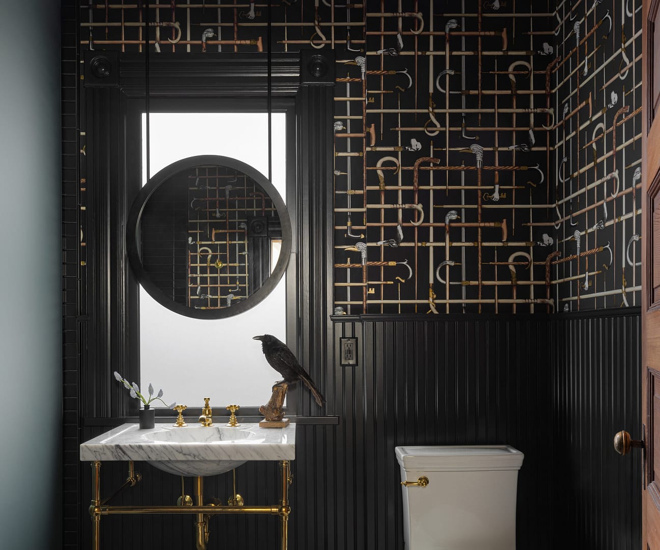
Built in 1899 in Portland, OR, this historic home is a Victorian Era gem and on the National Register of Historic Places. The home was previously remodeled and the primary suite in the