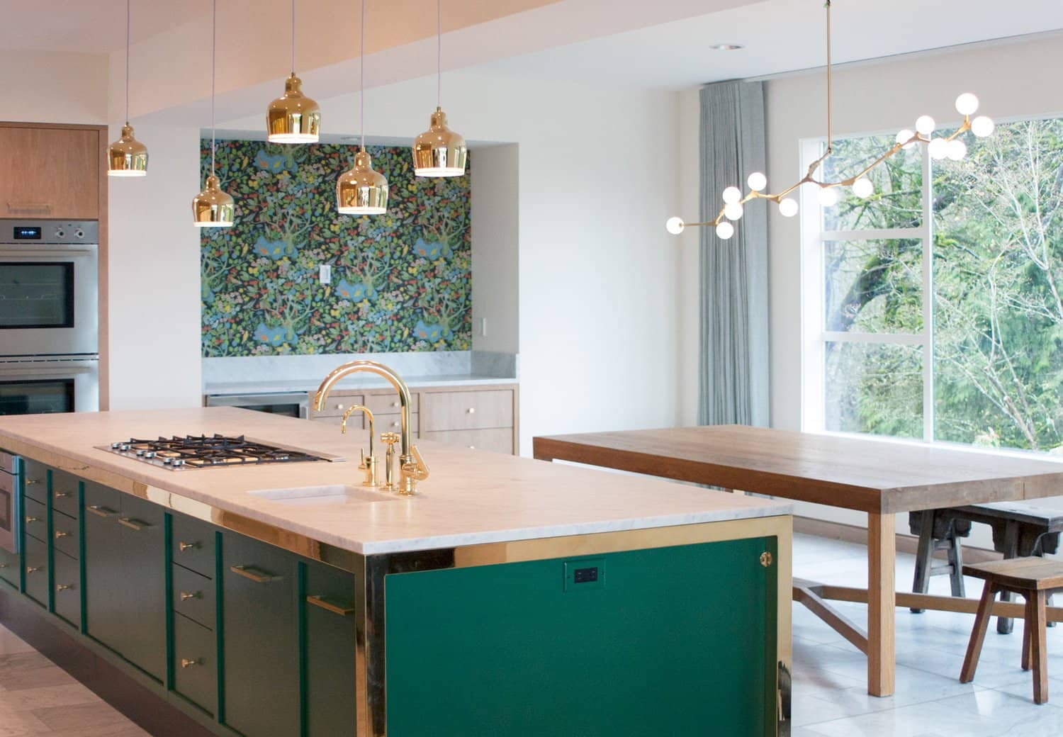
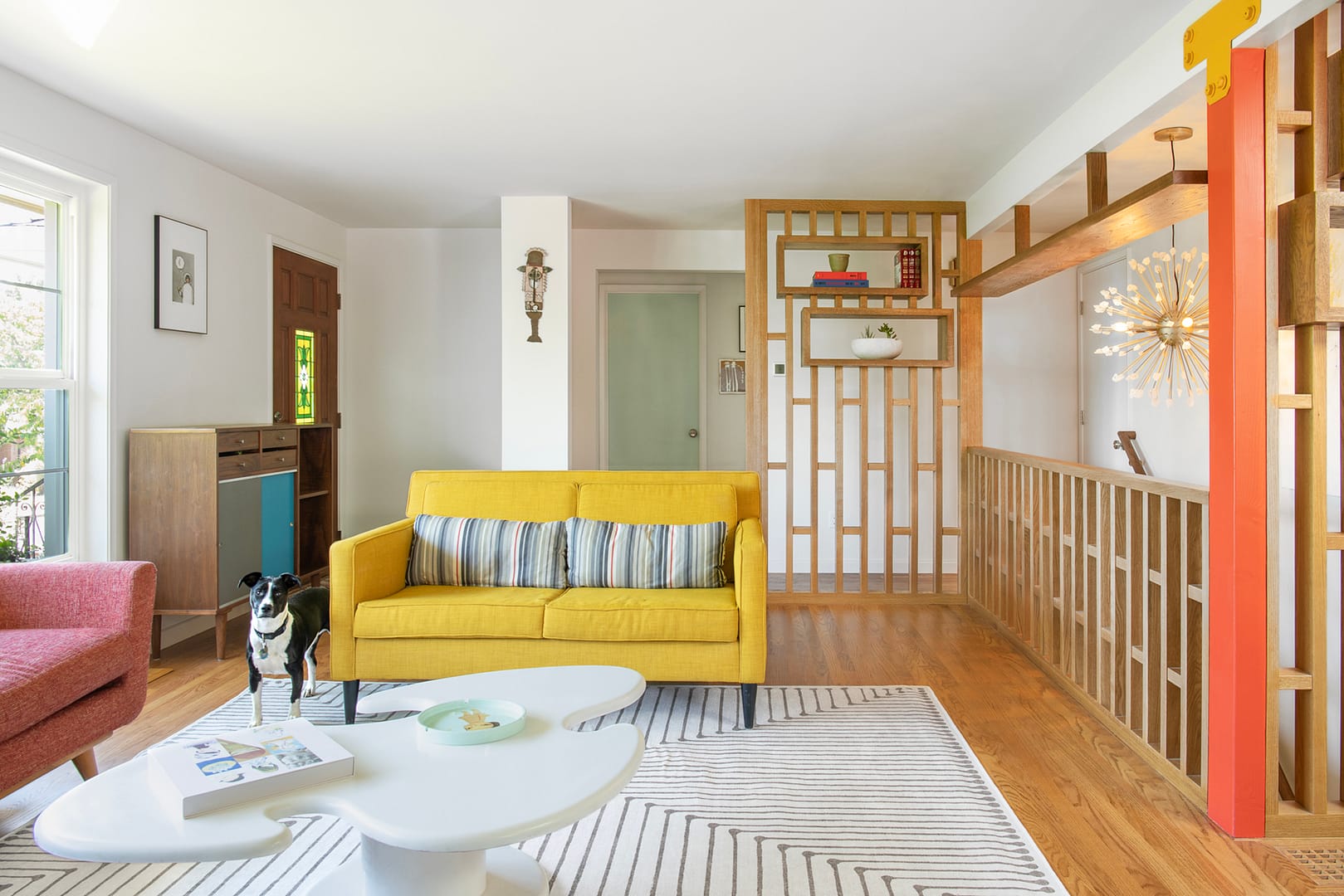
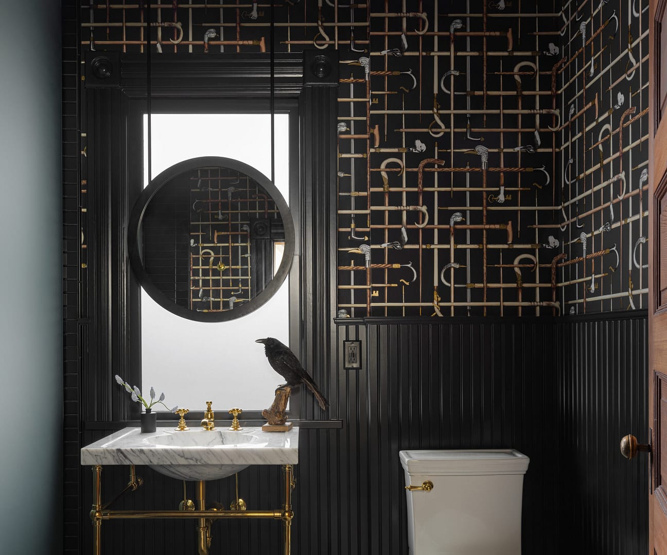
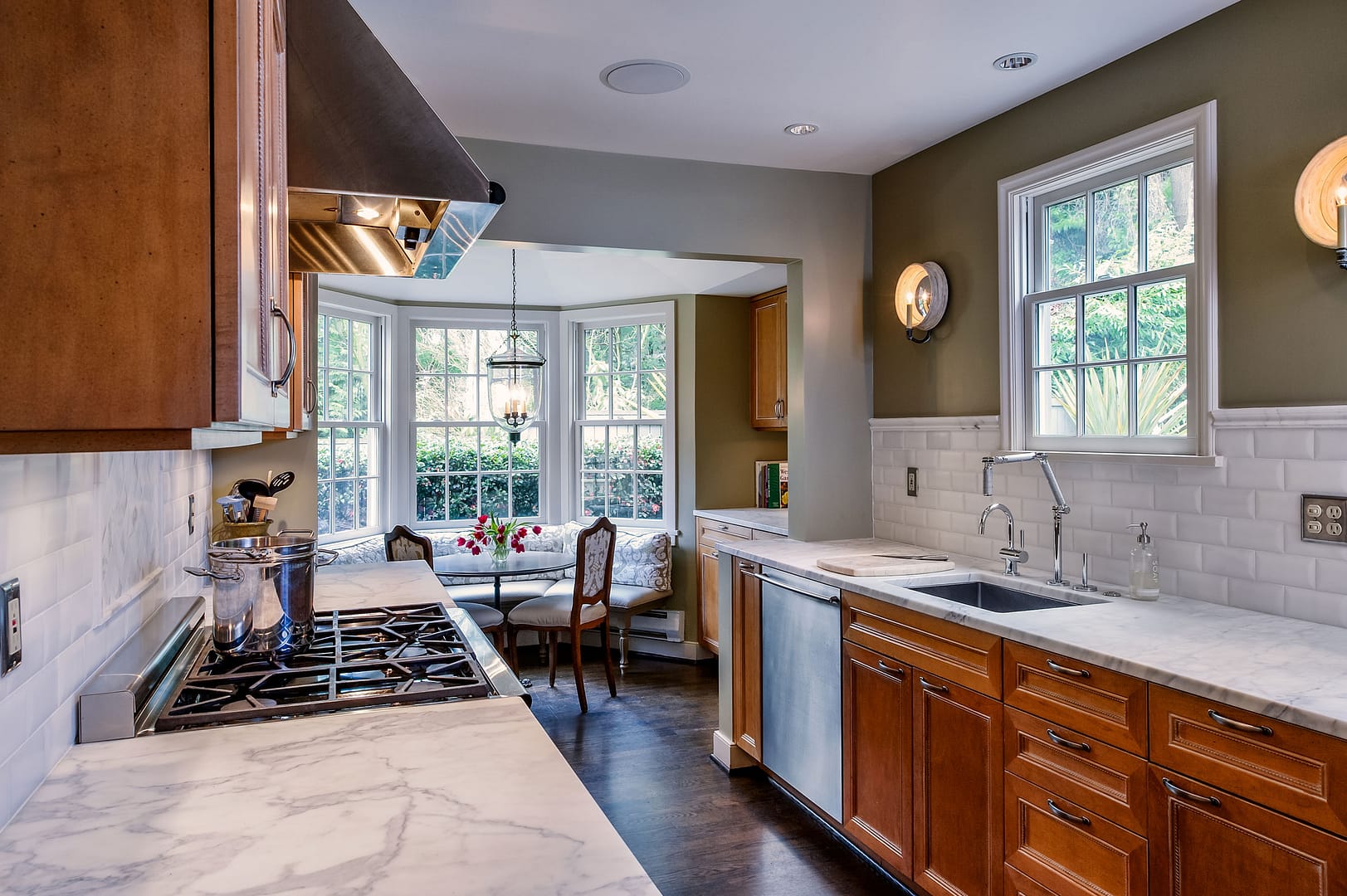
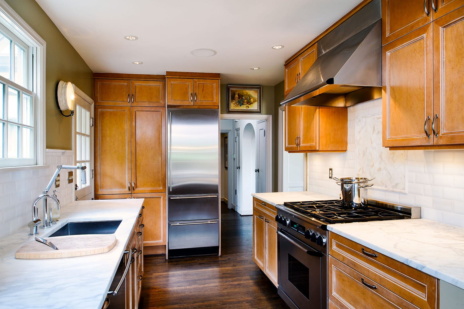
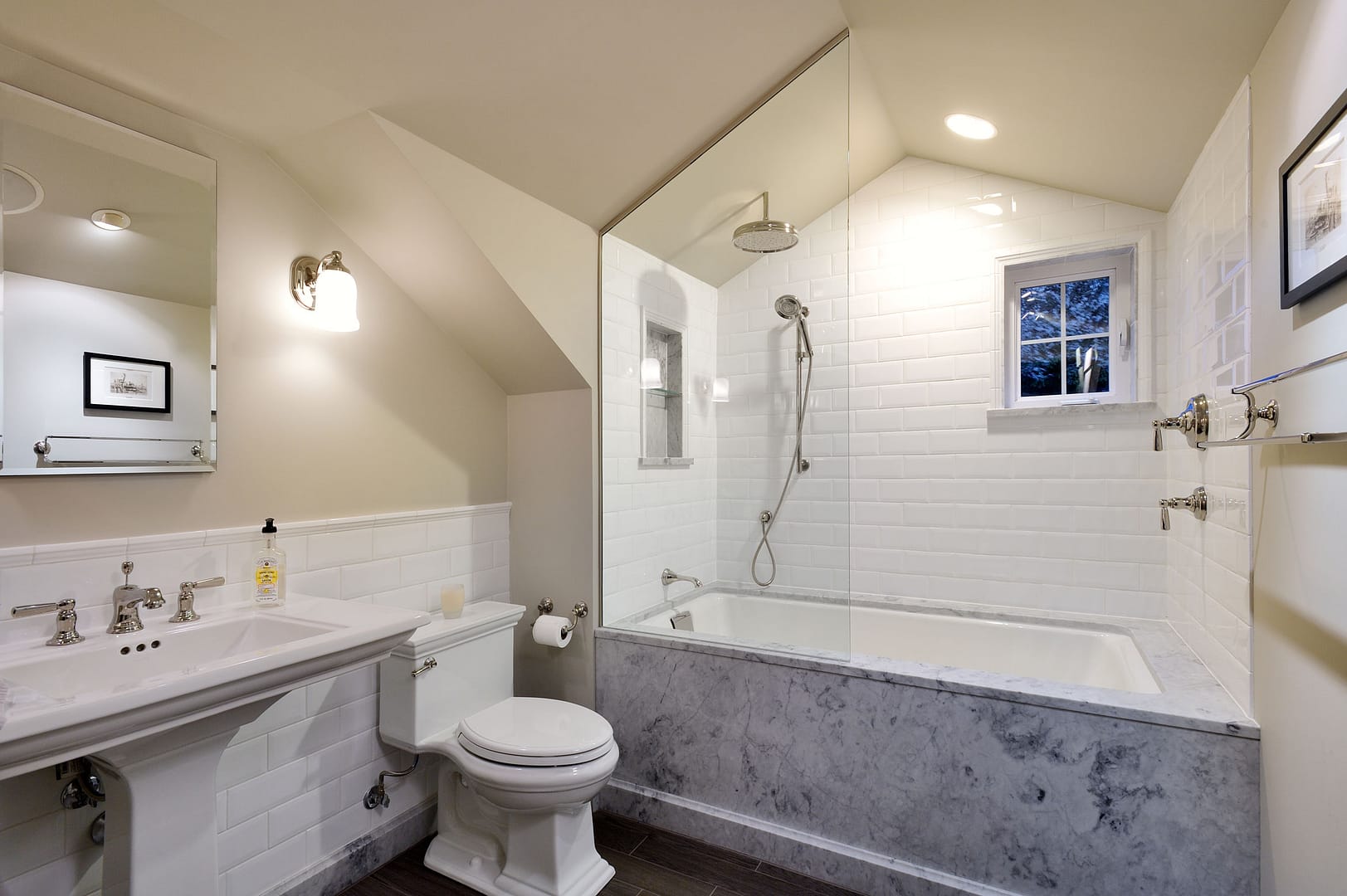
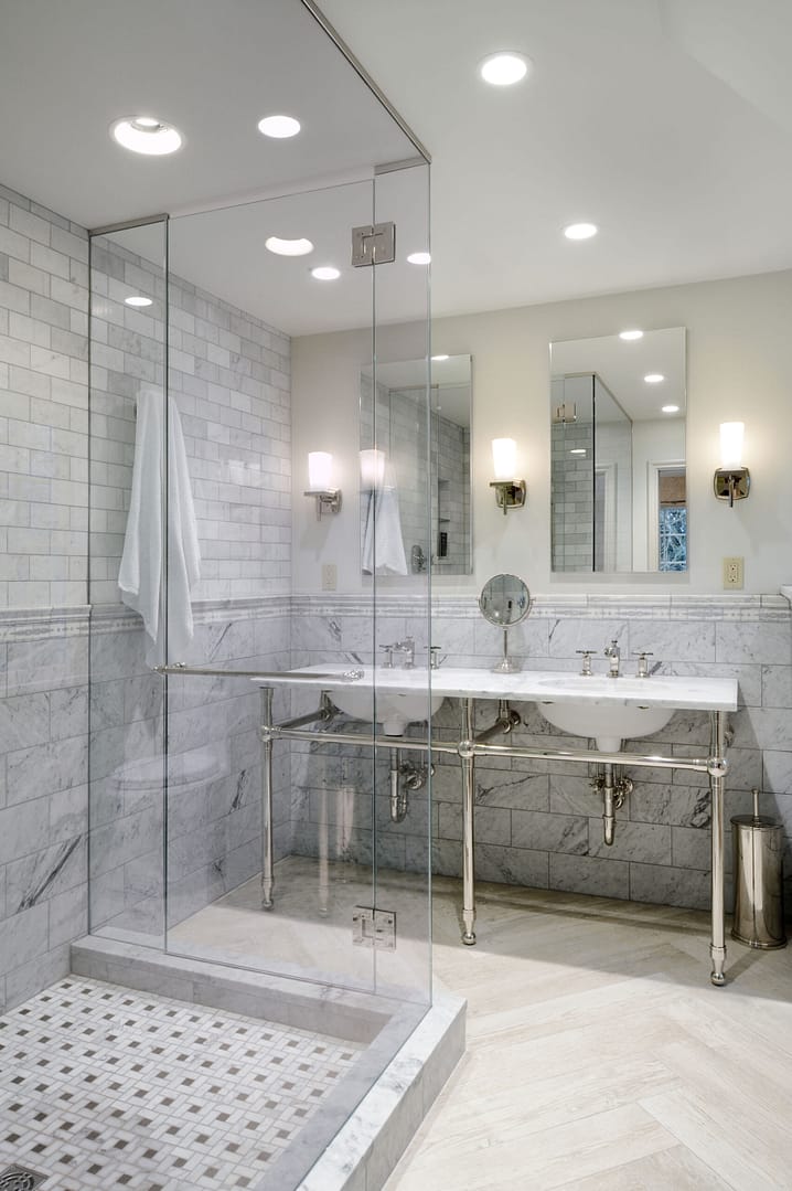
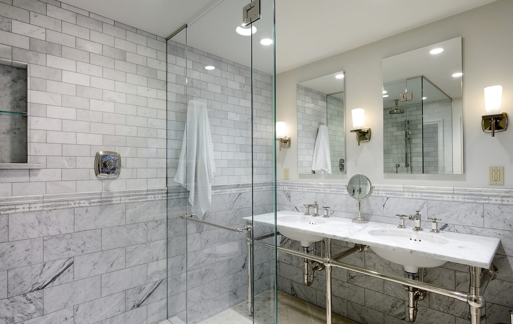
Easy customisation of the reinforcement preview in Advance Design reinforcement concrete design modules

2 November 2022Advance DesignBIM, Design, Structural Analysis

Partager

advance-design.jpg

Introduction

We probably don’t need to convince anyone that being able to see the reinforcement in 3d view while designing it is very helpful. It allows us to see where and what bars will be placed and how they are distributed in space, and thus we can easily see what we could normally only imagine. This is especially useful when we are still at the reinforcement analysis stage, where we can easily test different solutions without having to generate final documentation. Such views with reinforcement can also come in handy when creating documentation. Let’s take a look today at what RC modules of Advance Design offers us in this regard.

Views

We will start with understanding the views. RC modules display three types of element views by default: front view, section view and 3D view.

However, depending on the type of element (beam, column, foundation, wall, slab), we may have slight differences. For example, for foundations, a top view is available instead of a section, and you can additionally choose the viewing direction for the elevation view.

We can have each view displayed adjacent to other views, with the ability to resize them. We can also display the view in full-screen mode – just double-click on a view to change modes. The 3D view is used to view the resulting solution. In 2D views, in addition to the geometry of the elements and the reinforcement itself, bar descriptions and dimension lines are presented.

We can easily move and zoom the contents of the views using the scroll wheel and mouse buttons. In addition, in 3D views, we can use the View Box located in the corner of the view, so we can easily rotate the content and adjust the view

It is also worth mentioning that we can interact with objects from the views. First of all, we can highlight and select reinforcement, so that a tooltip will appear with information about the bars.

In addition, by double-clicking on some of the elements, we can edit them. For geometric elements, a dedicated dialog box will open. For reinforcement, the corresponding reinforcement editing window will open. And, for example, by clicking on a dimension line, we can directly modify a given value.

One of the great advantages of views in Advance Design modules is that they can be customized. These settings are mainly available from two places – as icons inside the views and global settings of the application.

Commands on views

Each view contains a number of commands in the form of icons located at its bottom. Some of the icons act as buttons for changing the display mode, while others call additional commands. The number and type of these commands can vary slightly depending on the type of view and the module type. Let’s see what most of these buttons are used for.

 – Measure distance.  This command allows you to measure the distance between two points. It is available on 2D views.
Show section box. This command is used to hide the object showing the position and size of the section. It is a blue box visible in the 2 and 3D views, which we can move with the mouse to change the position of the section visible in the section view. We can also modify the depth and position of the section directly in the section view using the fields at the bottom of the view.
Print and Save. These commands are used, respectively, to directly print a given view or save it in graphic file format.
Display mode. These buttons are used to change the way the view is rendered. It can be Wireframe – without shading, Flat rendered – with shading, and Realistic – with shading including lighting (only available on 3D views).
Show dimensions. These are commands for showing/hiding dimension lines. Depending on the view and module, different variations may be available. For example, for a column elevation view, we can show vertical dimension lines separately for geometry and for reinforcement layout.
Show viewport / Zoom all. These commands are available for all views and are used, respectively, to change the full-screen mode of the view and to zoom to fit the window size.
Show/Hide loads. A command that allows you to present the applied load. In the cases of beams and walls, you can additionally select the mode whether the loads are to be shown as overlapped or presented in layers, one above the other.
Show/Hide formwork. An interesting command that allows the presentation of the reinforcement itself without presenting the geometry of the elements. This view makes it easier to verify more complex bar arrangements and is only available for 3D views.
Show/Hide rebar annotation. This is a simple command to hide / show bar descriptions.

Display Settings

The settings described earlier are mainly used to enable/disable settings on views. Meanwhile, the configuration of the appearance and content of the displayed items is done in the dedicated Display Settings configuration window. These settings are global module settings and are retained.

We can distinguish three main groups of settings: Annotations, Colours and Visibility.

Annotation settings – settings for the appearance and position of dimension lines and the content of descriptions.

With these settings, we can configure how these items are displayed according to our preferences.

Colour settings – settings for customising the colour to be displayed in viewports for different categories of elements. In this process, we can choose any colour and degree of transparency.   Colour changes can be made for 3 main categories – geometric elements, reinforcement, and loads. For loads, we can set different colours for each type of load and load case family. For reinforcement, we can additionally decide on the colouring method – whether the colours should depend on the reinforcement function or be coloured by diameter.

Visibility settings – allows selecting which types of load cases, loads and reinforcement families will be visible on the model. Turning off the visibility of the selected graphic or category makes it invisible in the model, being useful when wanting to work in an unobstructed model.

For loads, the settings also include the ability to hide loads that are smaller than the entered limit. This makes it easier to view loads in case they have been imported from an FEM model and we only want to display key forces.

The settings described above not only allow you to easily customise your work environment to your preferences, but also make it much easier to view data and results, increasing your work efficiency.

Mateusz BUDZIŃSKI – Structural Analysis Product Line Manager

Any question?

Please contact us if you have any questions or requests on our products, training, consulting services or events. Our team of experts are here to help you get the best out of your projects.

Any question?

Related content

Solar Farm and Ground Solar Power Plant: Everything You Need to Know

2 July 2024Advance Design, Renewable energy, Solar Panels, SustainabilityLukasz Jedrzejewski

Learn all about photovoltaic solar farms, their advantages, and their structures for an ecological and profitable photovoltaic park

Photovoltaic Shade for Car Parks: All You Need to Know

26 June 2024Advance Design, Solar Panels, SustainabilityLukasz Jedrzejewski

Car parks take up a lot of space. Shifting energy production to renewable methods is necessary. Combining these trends, photovoltaic…

Metal Structure for Solar Panels: What You Need to Know

20 June 2024Advance Design, Renewable energy, Solar Panels, SustainabilityLukasz Jedrzejewski

Discover all the essentials about metal structures for solar panels: Types of structures, benefits, installation calculations, and more.