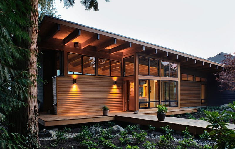
New entry, remodeled bathroom, refined layout, and kids loft deliver big benefits with small SF.
“It’s not a very big addition,” said Hammer & Hand lead carpenter Scott Gunter, “but it packs a lot of punch.”
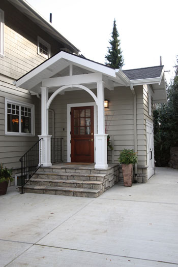 The owners of this 1910 home in Portland’s Southwest Hills neighborhood had three problems on their hands: damaging water leaks in their basement, poor circulation around the kitchen and rear entry, and limited indoor space for kids to play. So they approached neighbor Ann McCulloch of Ann McCulloch Studios to design a mudroom/bathroom/landscape solution and contracted Hammer & Hand to build addition remodel.
“I loved working with the clients,” said Scott. “They have two great kids, and Sandy was always making us fantastic snacks, brownies, cinnamon rolls, you name it. Really great people”
See this video of the clients’ kids singing their “Hammer and Hand song”:
Scott was joined onsite by Hammer & Hand’s Bobby Pinkham and Matt Ashjian, with Aaron Quint performing installation of the custom railing and ladder built in our woodshop by master jointer Dan Palmer.
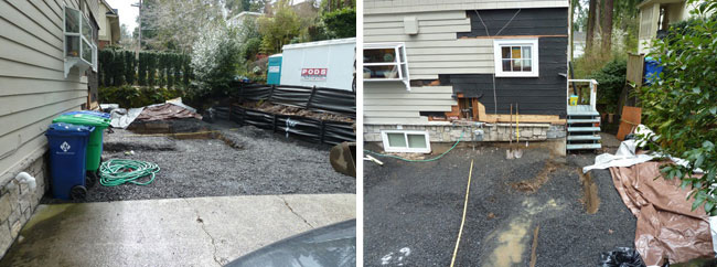
“before” photos courtesy of client.
The first order of business was to rip out the existing driveway, a severely cracked concrete stretch that sloped toward the house, dumping a flood of rainwater toward the basement with each storm.

Our team poured a new driveway, this time sloped away from the house and properly drained. Jeff Coleman Masonry rebuilt a basalt retaining wall and installed the landscaping for the project.
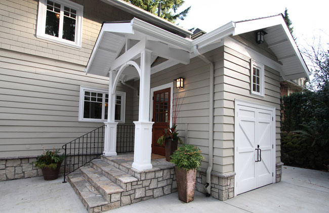
“after” photos by bright designlab.
Ann McCulloch designed the mudroom addition as a natural extension of the house, one that maximizes limited space.
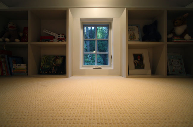
“We used every bit of space on this addition,” said Scott. “Those carriage house doors on the exterior open into a storage space for garden tools and equipment. The ceiling of that storage space becomes the ‘floor’ of the kids’ loft space. And the mudroom itself creates inside/outside connections and circulation to the kitchen. It’s really well designed.”
McCulloch was careful to incorporate architectural detailing from the house into the addition. On the exterior siding, a “belly band” of wider wood continues from the house and transitions to a white color as it wraps around the top of the addition’s exterior walls.
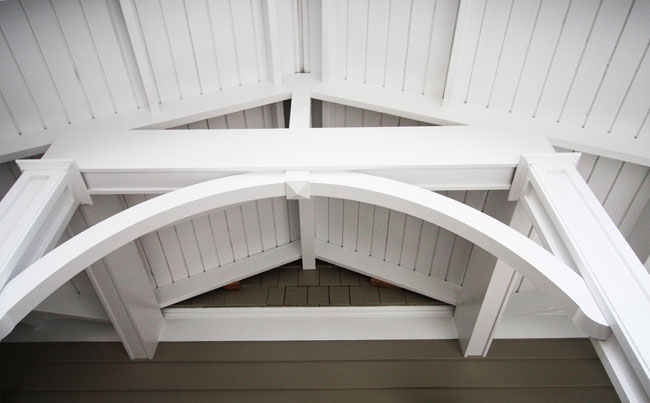
Details for the house’s eaves are pulled into the porch and eaves of the addition, including the 3′ overhang, the open framing, the tongue-and-groove ceiling and the shingle detail under the peak of the eaves.
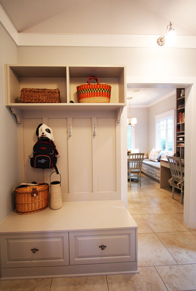
And this care for detail continues inside. The wainscoting throughout the mudroom matches existing design details from the house.
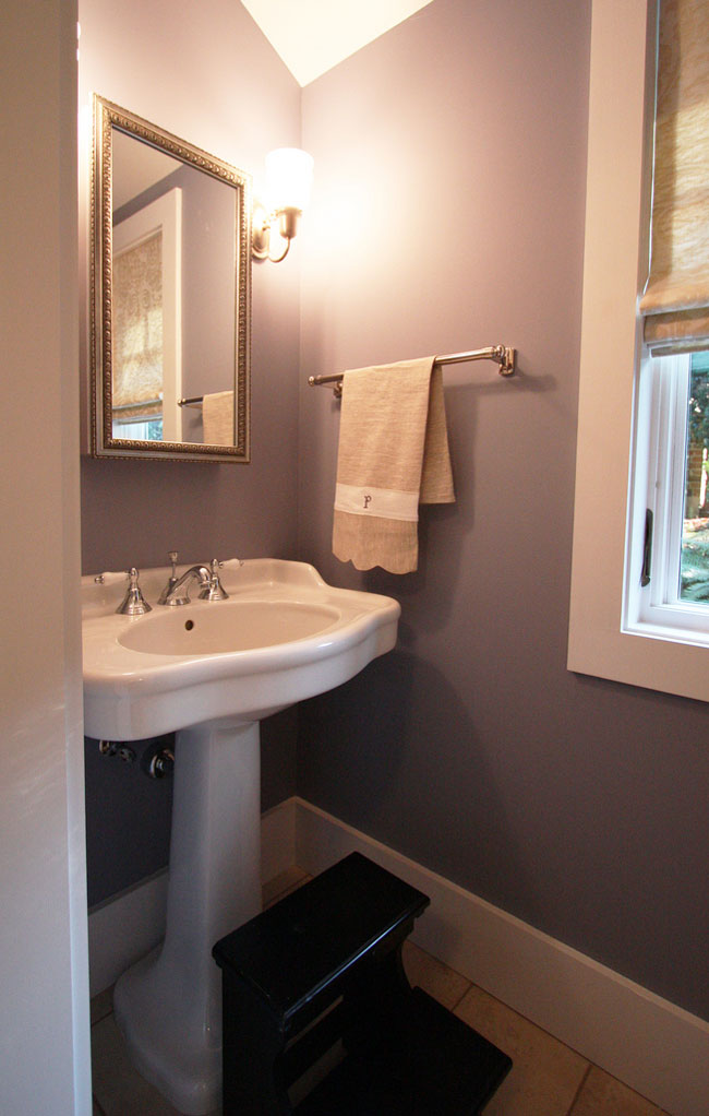
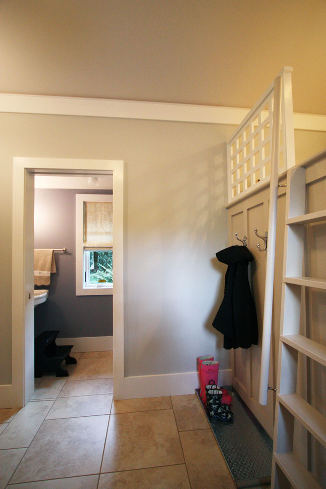
The newly remodeled powder bathroom’s fixtures and trim respect the home’s architectural heritage.
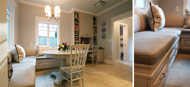
The lines of the built-in banquette, cabinets and shelving of the eating area take strong cues from the existing house.
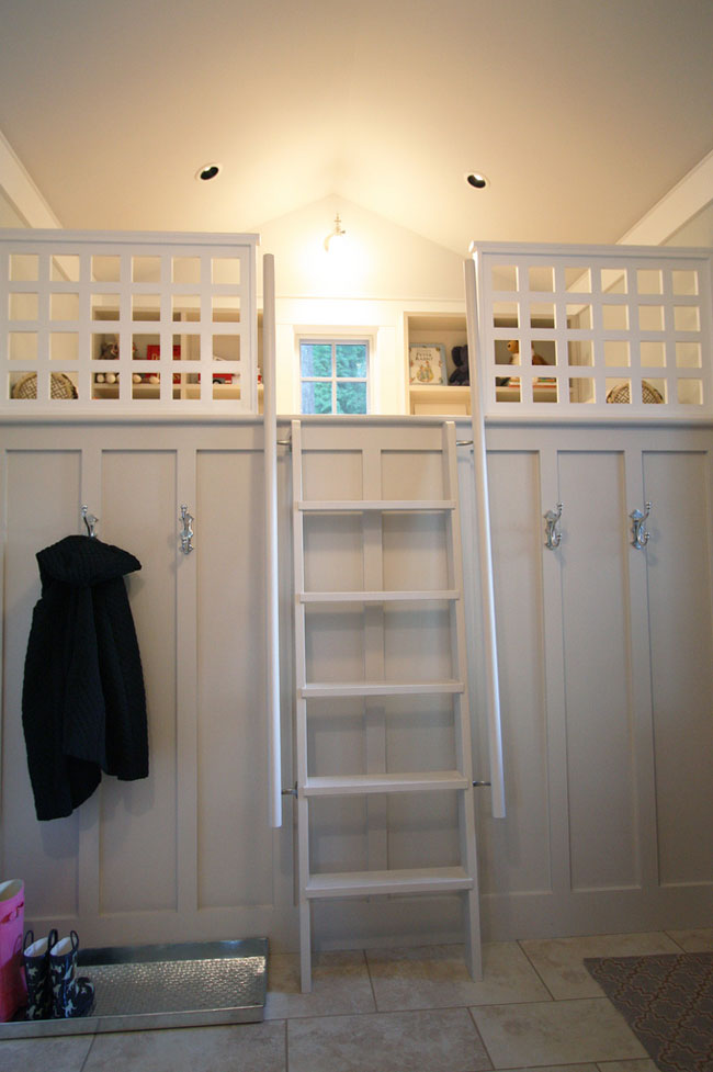
And the custom-built ship’s ladder and rail that leads to the kids’ loft carefully complement the wainscoting design.
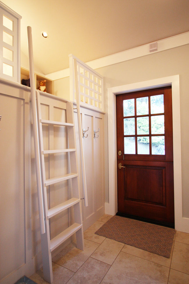
“I was so impressed with how well the details and the spaces of the addition interact with the kitchen and connect it all with kids’ space and outdoors,” said Scott. “It’s a really elegant solution.”
The addition’s dutch door plays an understated but important role in this success. The homeowners’ original hope was that their home’s pre-existing rear dutch door be incorporated into the new addition, but layout and dimensions precluded that. The new door fulfills the original intent: to increase the home’s connection to the outdoors and facilitate parents’ access to children at play.
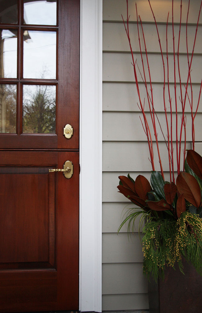
It’s a nice final touch to a successful addition and remodel.
P.S.
Check out this article in The Oregonian about the project.
